We’re back with Part III of our Dart University series, in which we enlist the aid of some of the best in the business to help us learn the ins and outs of putting together anything from a hot street engine to a full race motor. As always, Dart’s Jack McInnis will be our guide, taking us through a few of the many bits of wisdom the company has accumulated through their years of competition experience. This time around, we’ll be looking at how to degree a cam, checking piston-to-valve clearance, and how manufacturing tolerances affect your build.
CAM DEGREE VIDEO PLACEHOLDER
How to Degree a Cam
One of the things you’ll often hear engine builders talking about when discussing optimizing an engine’s performance is “degreeing the cam,” but what that really entails isn’t necessarily obvious from that description. In a nutshell, degreeing is a process that determines the camshaft’s exact relationship to the crank, making sure that their centerlines are precisely aligned. If the camshaft is positioned incorrectly, it defeats the efforts of the cam designer to time valve events properly, and more importantly, it can also lead to contact between the valves and piston tops.

Step one is determining Top Dead Center for the #1 piston, because all the other measurements depend on setting this accurately. It can be done in a couple of different ways, both with the heads on or off. Per McInnis, “The piston stop is the most consistent method. A dial indicator offers too many opportunities to make an error for the average person.” As far as doing it with the long block assembled, McInnis doesn’t recommend it. “Spark plug hole stops are not very good in my opinion – they are too easily bent or deflected.”

Once the crank centerline is found, judicious use of a dial indicator on the camshaft lobe will allow you to find the cam’s centerline as well. Armed with that information, you can determine whether the cam is “straight up”, or if the manufacturing tolerances in the camshaft, crank keyway, and timing set have moved the centerline forward or backward from true zero. An adjustable timing set, either with multiple fixed keyways or an adjustable gear with setscrews, can bring things back into line or adjust the timing ahead or behind.

“Generally, retarding the cam will move the power band up the rpm range, while advancing it will move the power band down,” McInnis explains. If you know what you’re doing, moving cam timing around can provide a chance to experiment with fine-tuning the engine without the trouble of a full cam swap, but it’s not necessarily a good thing for beginners to mess with because of the possibility of getting into piston-to-valve interference. McInnis concludes, “This is loaded with variables and really not recommended for the typical do-it-yourself guy.”

VALVE CLEARANCE VIDEO PLACEHOLDER
Checking Piston-to-Valve Clearance
Most of the time when building an engine for the first time, swapping heads on an existing motor, or changing cams, piston-to-valve clearance won’t be an issue. But when you get a lot of lift, high-compression pistons, aggressive cam timing ahead or behind the straight up position, or a combination of the above, it’s important to check just how much room you have. You might think that as long as everything turns over by hand without going “thunk” you would be OK, but heat causes tolerances to shift, and the dynamic forces on the pistons, valves, and timing gear can cause things to get a little too intimate in operation.

To check valve clearance, you’ll need to mock up your long block and valvetrain, and grab some modeling clay. By sticking chunks of clay to the piston face over the valve notches, you can assemble the head to the engine, put together the valvetrain for that cylinder, and take it through two turns on the crank to create valve impressions in the clay. Carefully cutting and measuring the compressed clay will allow you to determine the actual clearance and decide if you’re good to go.

Of course, to make the process work, you need to make sure your mockup is dimensionally the same as the engine will be in operation. That means that hydraulic cams (roller or flat tappet) will need to be checked with a solid lifter that has the same length as the hydraulic piece, but McInnis assures, “Typically, the height of the lifters will be the same for comparable hydraulic and solids.” You also need to make sure the head gasket thickness is correct; for new builds, a fresh gasket torqued to the correct specs, or per McInnis, “Snug with a used (compressed) head gasket is fine.”

With the impressions made and the head back off, carefully sectioning the clay and measuring with a caliper will tell you whether or not you have enough clearance. “A good safe spec is .060″ intake, .120″ exhaust,” McInnis explains. “Absolute minimum is .030″/.090″. It is more dependent on rod stretch at the operational RPM range than being RPM-specific. Valve float is also problematic if it should occur.”
It’s also worth pointing out that you need to check both face clearance (the distance between the flats of the piston valve relief and the valve itself) and the radial clearance between the edge of the valve and the edge of the relief. Using clay impressions lets you literally dissect the clearance and see what’s really going to happen when the engine runs.

For critical racing applications, you can also check clearance by omitting the clay and using a dial indicator on the nose of the rocker arm. With check springs installed, you can turn the engine over one degree at a time and manually compress the valve until it makes contact, then read the available clearance off the dial indicator. By working methodically through the valve lift duration, you can plot the clearance at all points and even check to see the effects of advancing or retarding cam timing.
MANUFACTURING TOLERANCES VIDEO PLACEHOLDER
Manufacturing Tolerances and Engine Blueprinting
One of the things that separates a top-quality build from one that’s just average is attention to detail, and that starts from the bottom up with determining just how close to spec your components are. No manufacturing process is perfect, and every single part of your engine will have tolerances plus or minus from the dimensions on the engineering blueprint. While some imprecision is inevitable, reducing it in the first place is a worthwhile goal, and awareness of your components’ true dimensions is the key to a trouble-free build.

At Dart, the process begins with the way they track everything all the way through production. Buy one of their blocks, and you will get an information package that details what its true dimensions actually are, not just what they should be. Of course, sticking close as possible to those ideal numbers is their goal as well, and when you order up a prepped block from Dart instead of having the machine work done locally, you gain another important advantage.
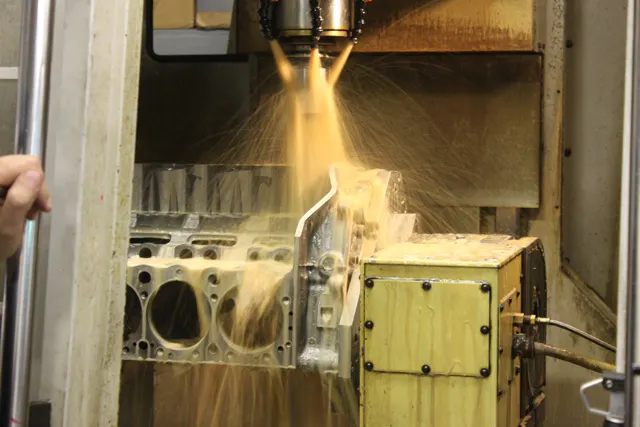
Besides the fact that nobody knows how to line hone and deck a Dart block better than Dart, they’ve also got a lot more invested in hardware than even the most well-equipped independent machine shop. Instead of a Bridgeport mill, you’re talking about multi-axis CNC machine centers – the “tombstone” fixture that Dart uses to mount blocks for machining outweighs some conventional mills all by itself! That hardware translates into both closer tolerances due to increased precision, and fewer chances for “drift” due to multiple setups.

The process doesn’t end once your block leaves Dart, though – Once it’s in your hands, it’s time to break out the bore gauges and micrometers to check the individual components of your rotating assembly against the published specs and compare them to your finished block. Keeping an eye on piston-to-bore clearance, rod dimensions, and the main/crank/bearing relationship will avoid problems down the line and give you a baseline for reference the next time you take the engine apart for freshening.
With that, our first series of Dart University articles and videos is complete. That doesn’t mean there’s nothing left to learn, though – visit their website at www.dartheads.com to stay in the loop as they add new information to fulfill your continuing education goals. Remember, kids – education is a journey, not a destination!
You might also like
Classic Style, Modern Control: Art Morrison’s GT Sport Chassis For Early Chevys
Art Morrison's GT Sport chassis transforms the timeless 1949-54 Chevrolet into a serious restomod performer.