High-performance vehicles seem to excel at offering a never-ending process of challenging the builder on how to more efficiently spend his time working on these machines. This process constantly evolves, because as our experience grows, technology is also changing. Sometimes, we just have to learn the hard way by making mistakes. We’ve learned almost as much about how to work on cars by making mistakes (and witnessing the miscues of others) as we have from the few successes we’ve enjoyed. That falls under the category of life lessons, which we’ve distilled down into bite-sized tech tips.
The following tech tips, like the previous ones we’ve published, are lessons we’ve learned over the decades of spinning wrenches and discovering the right way to do things. You may find a few of these helpful, and that will make the process of working on your car more enjoyable. That should be the whole point of all the time spent draped over the fender of your car. It’s all aimed at the quest of having fun with cars. At least that’s what it’s supposed to be!
Be Careful When Disabling the Ignition
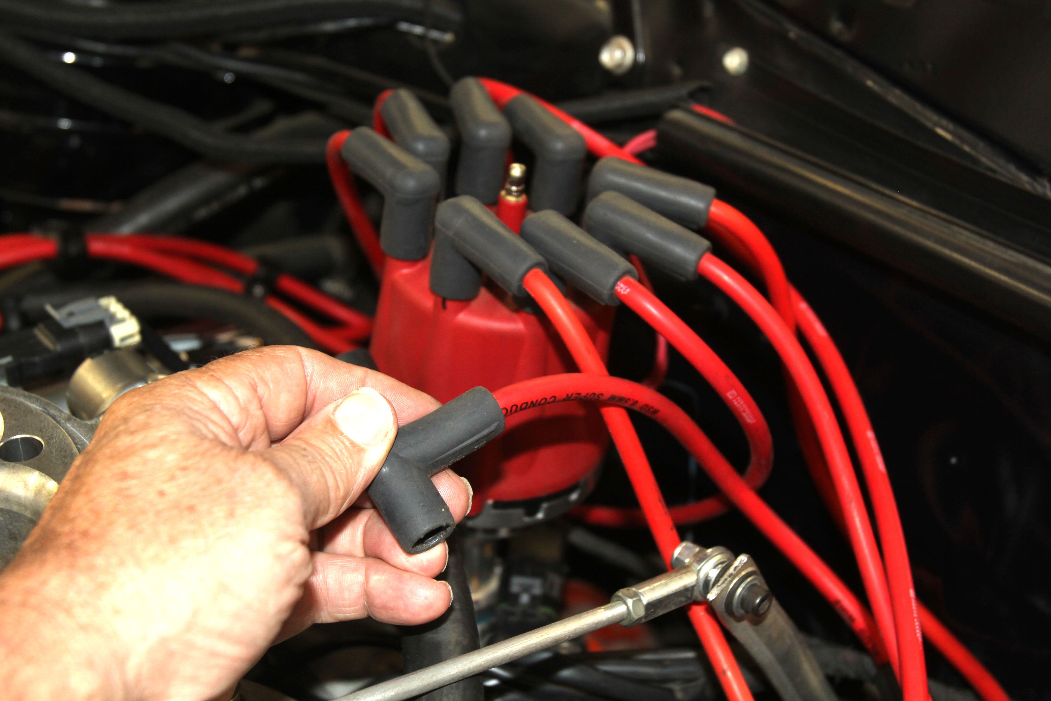
We were working on changing pushrods in a small-block Chevy and decided to disable the ignition by pulling the coil wire. Unfortunately, we pulled the high tension wire out of the coil instead of out of the distributor cap. Then while cranking the engine to set lash, the coil fired and the spark jumped to the negative terminal of the coil and zapped the electronic point conversion kit in the distributor.
This required replacement of the entire conversion kit. The lesson was obvious; when disabling the ignition, pull the coil wire from the distributor and ground the wire to the engine. Or disable the coil by disconnecting power to the positive side of the coil. This will protect the ignition module from damage. This is sound practice for any ignition.
LS Lifter Tool
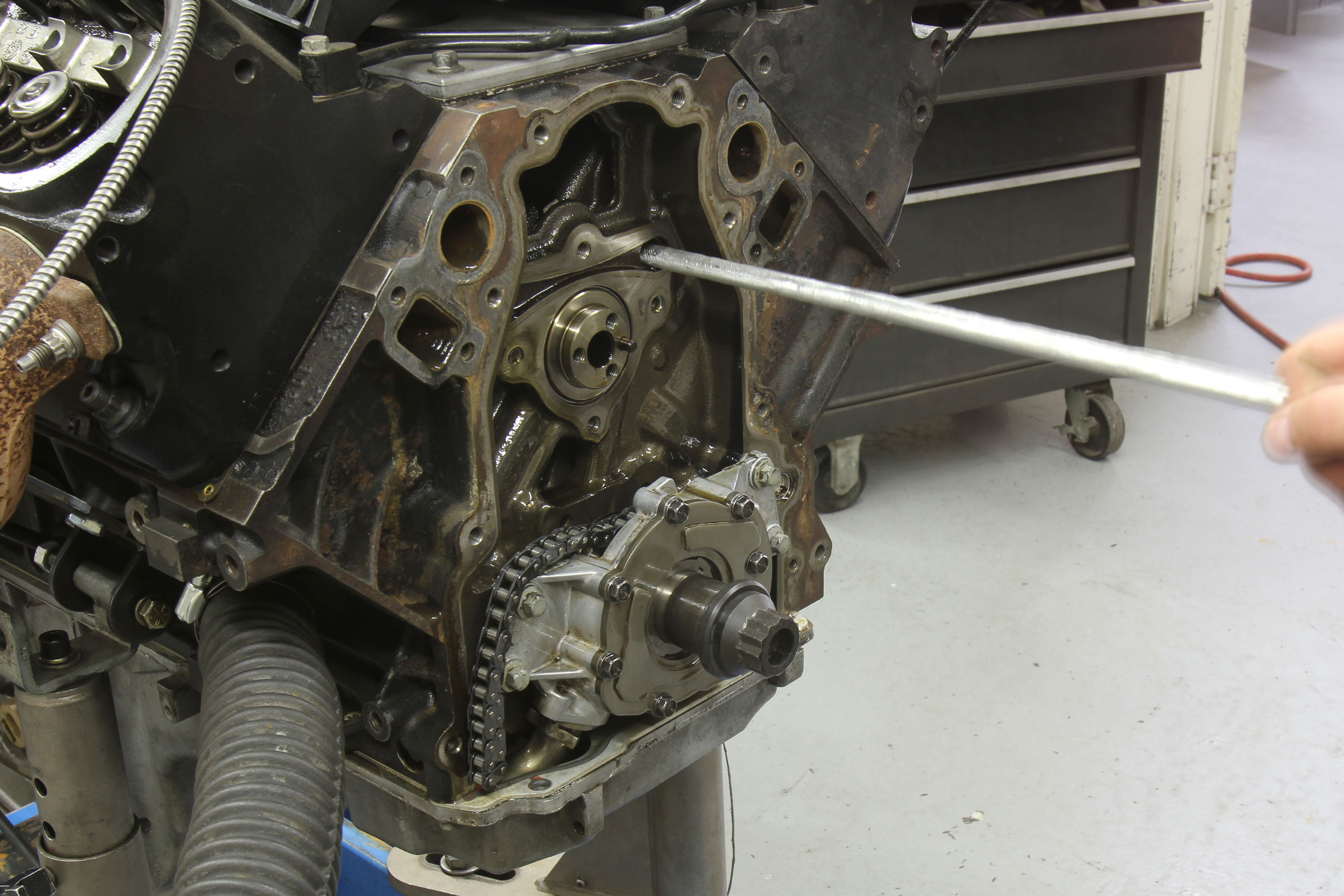
Most everybody knows that when swapping cams on an LS engine, after the rockers and pushrods are removed, you can spin the engine over several times and the hydraulic lifters will move up out of the way of the cam lobes to be retained by the factory plastic lifter trays. With new trays, this works very well. But older LS engines with a ton of heat cycles will often drop a lifter, which if you’re unlucky, falls into the oil pan which is a ton of extra work to retrieve. This tech tip should help you avoid that.
The best way to avoid this problem is by using an aluminum or steel dowel rod you can push down the length of the lifter galley to hold the lifters in place. We learned this trick from the Westech guys during an early LS engine cam swap. They used a round 5/16-inch dowel rod, around 30 inches in length. Sometimes it might be difficult to slide the rod past the lifters, so Westech made their tool out of aluminum rod as seen in the photo with a flat ground on one side. You can make your own tool from a length of 5/16-inch steel dowel rod or Powerhouse offers a tool (P/N POW-101046) available through Summit Racing.
How to Measure Pushrod Length
Measuring pushrod length is not as simple as just measuring the ends of the pushrod. Pushrods are actually measured from the middle of the tip radius. The guys at Trend Performance tell us the most accurate way to measure length is to use two washers with 0.140-inch holes drilled in them. The holes will locate over the end radius and then you can use a dial caliper to measure the length. Then subtract the thickness of the two washers and you have the accurate pushrod length.
We tried this with a marked 7.350-inch LS pushrod. We used two 0.020-inch washers with the proper hole diameters and the length came out to 7.406-inches. Subtracting 0.040-inch from the measurement equaled 7.366 or 0.016-inch longer than the indicated length. We’ll assume that our accuracy was within 0.010-inch, which should be more than sufficient.
Gen-V Tricks

When GM redesigned the LS engine as the Gen-V LT direct injection engine, it might be best to view this engine as a separate branch of the small-block tree. The motor mount pattern is different, the 12 o’clock hole for the bellhousing pattern moved slightly to the passenger side to accommodate the high-pressure fuel pump, and perhaps the most significant changes (beside direct injection, of course) is something that has not received much attention.
The Gen-V engine valve layout is different than in previous generations. The Gen-III/IV engine cylinder head valve layout (lower head in the photo) placed the intake valve at the front to create an I-E-I-E-I-E-I-E. The Gen V heads (the right head in the photo) switches this orientation or E-I-E-I-E-I-E-I. This also dictates the camshaft lobe layout. While this is not a life-altering tech tip, it is worthy of mention because it limits interchangeability between the Gen-IV and Gen-V engines.
Trust the Thrust
For checking thrust clearance, install the upper shell half in the block and with a front main bearing shell half, gently drop the crank in place and measure endplay. Then install the thrust bearing in the cap but before torquing the main cap, tap on the rear of the crank flange to align the rear thrust. Then torque the rear cap. Now measure the thrust clearance. If the clearance is too tight, sometimes aligning the two thrust bearings with the forward tap of a soft hammer will improve the endplay.
If the endplay is still too tight, remove the two thrust bearings and assemble them as a unit and hold them in place with a large hose clamp. Make sure they are completely even before tightening the clamp. Measure the overall width of the thrust with a dial caliper in several clock positions to find the high spot(s) and sand with 400 grit wet-dry sandpaper on a smooth, flat surface using Marvel Mystery oil as a lubricant. It’s best to sand only the forward portion of the bearing.
This will leave more material at the rear where most of the wear will occur. Mark the bearing with a Sharpie where the high spot is and sand it to create at least 0.001-inch more clearance than the minimum. The generic end play spec for a small-block Chevy is 0.003 to 0.011-inch. Clean the bearings thoroughly before reinstalling. We use rubbing alcohol and white paper towels and keep cleaning until the paper towel no longer shows grit.
PCV Leak Check
A quick check for whether your positive crankcase ventilation (PCV) system is working is if your dipstick is pushed out of the tube. That’s a classic indication that the engine is suffering from excessive crankcase pressure. This is bad, because that pressure will also push oil past the seals and leak all over your nice engine compartment. We’ve found that M/E Wagner’s billet aluminum PCV valve offers enough adjustability to create a small amount of vacuum in the crankcase.
This vacuum will minimize oil leaks at part-throttle for street engines. If all PCV valves worked like they are supposed to, this would not be necessary. But this valve solves the problem of most PCV valves working perhaps half the time. You can find this adjustable PCV valve at MEWagner.com. Its real claim to fame is that it minimizes or eliminates oil leaks in notoriously leaky engines.
Don’t Hesitate
On the internet, it seems that the suggestion for nearly every question concerning an off-idle hesitation is to recommend a 50cc accelerator pump for any Holley carburetor. In our 40-plus years of tuning carbureted small- and big-block street engines, we can say with absolute clarity that we’ve never seen the need for a 50cc pump. In some cases, off-idle hesitations are caused by ignition problems that are assumed to be carburetor-related.
The best place to start is to return to the stock, factory accelerator-pump nozzle size on the carburetor and make sure the entire system works properly. A very common issue is excessive clearance between the accelerator pump arm and the accelerator pump cover lever that allows the throttle to move quite a bit before the accelerator pump diaphragm begins to operate. Make sure the accelerator pump arm squirts fuel the moment the throttle moves and this will help eliminate most off-idle hesitation issues.
Easy to Miss
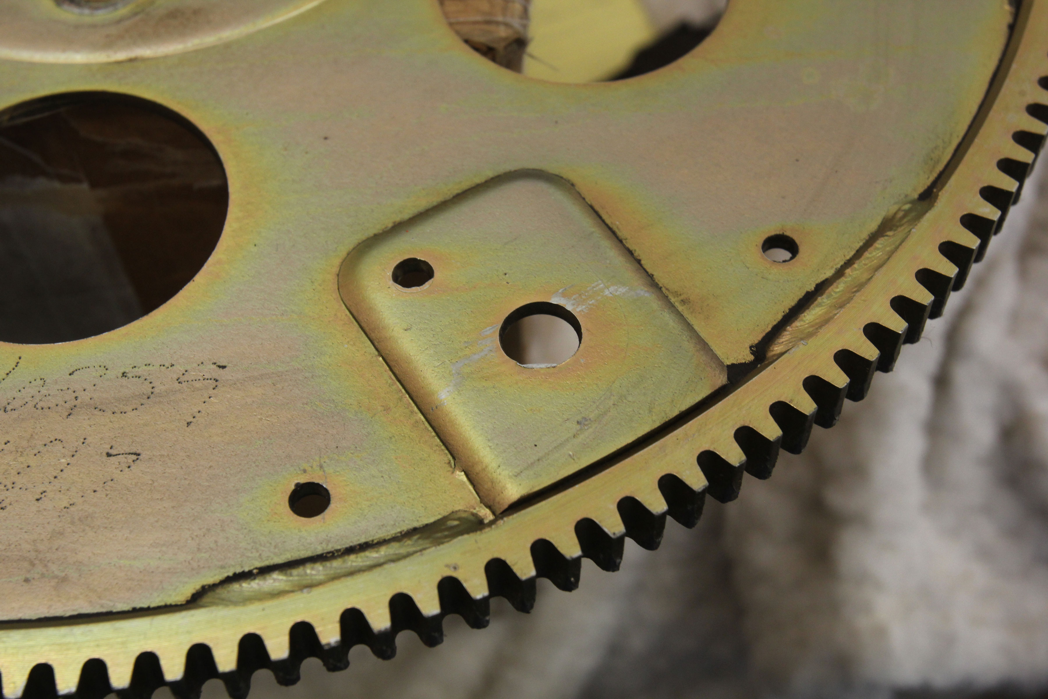
We have to admit, we made this mistake once. In a hurry, we bolted the flexplate onto the engine backwards and if you don’t catch the error in time, you will have to remove the trans in order to correct the error. Always install the flex plate with the raised pads facing away from the block (towards the converter). This is especially important if the flexplate is in backwards on an externally balanced engine, because the flexplate’s external weight will not be in its proper location and the engine will vibrate.
Injector Electrical Connectors
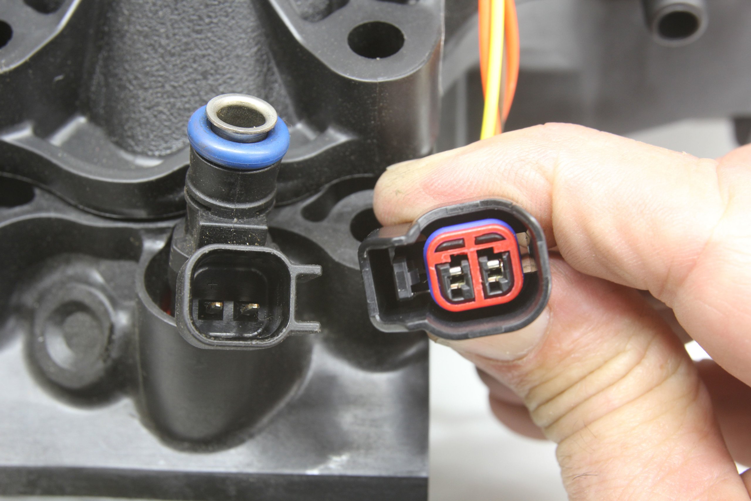
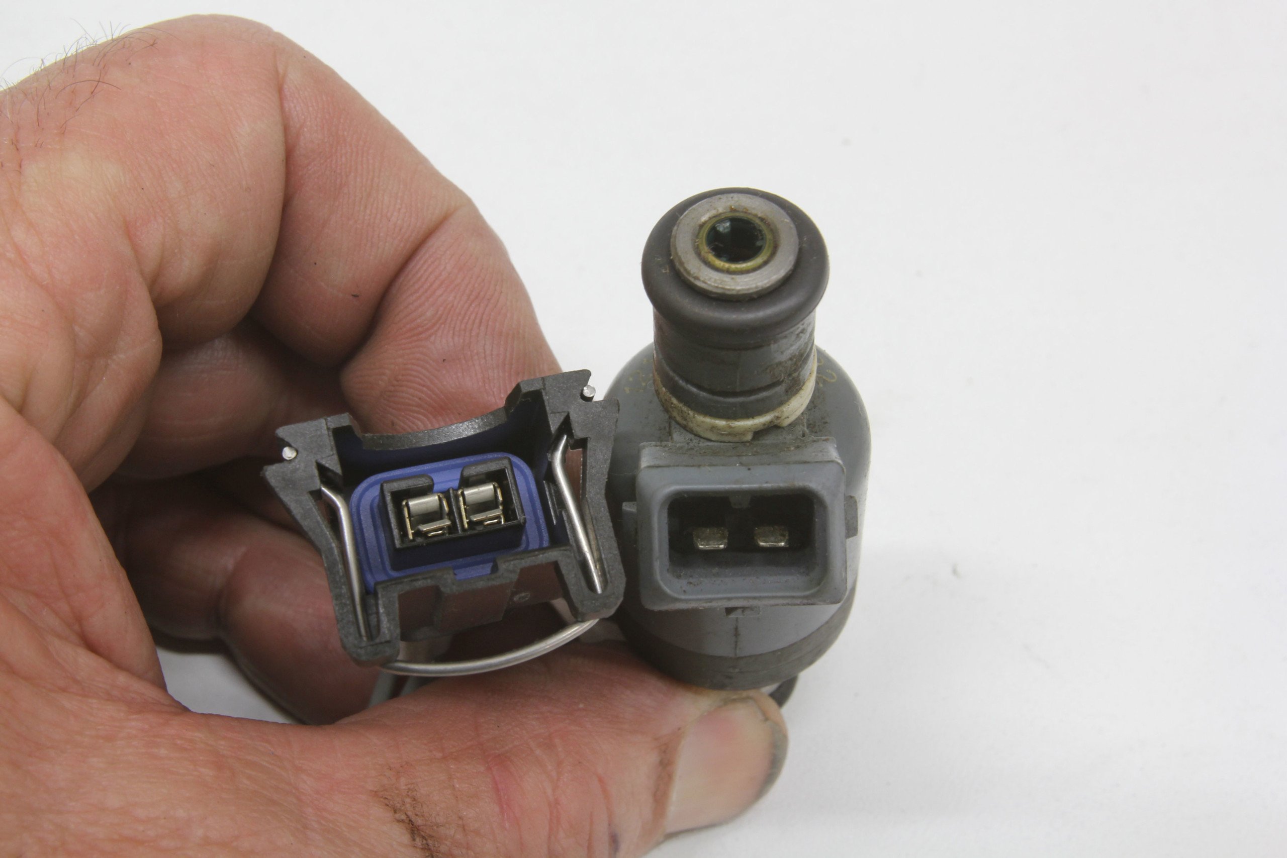
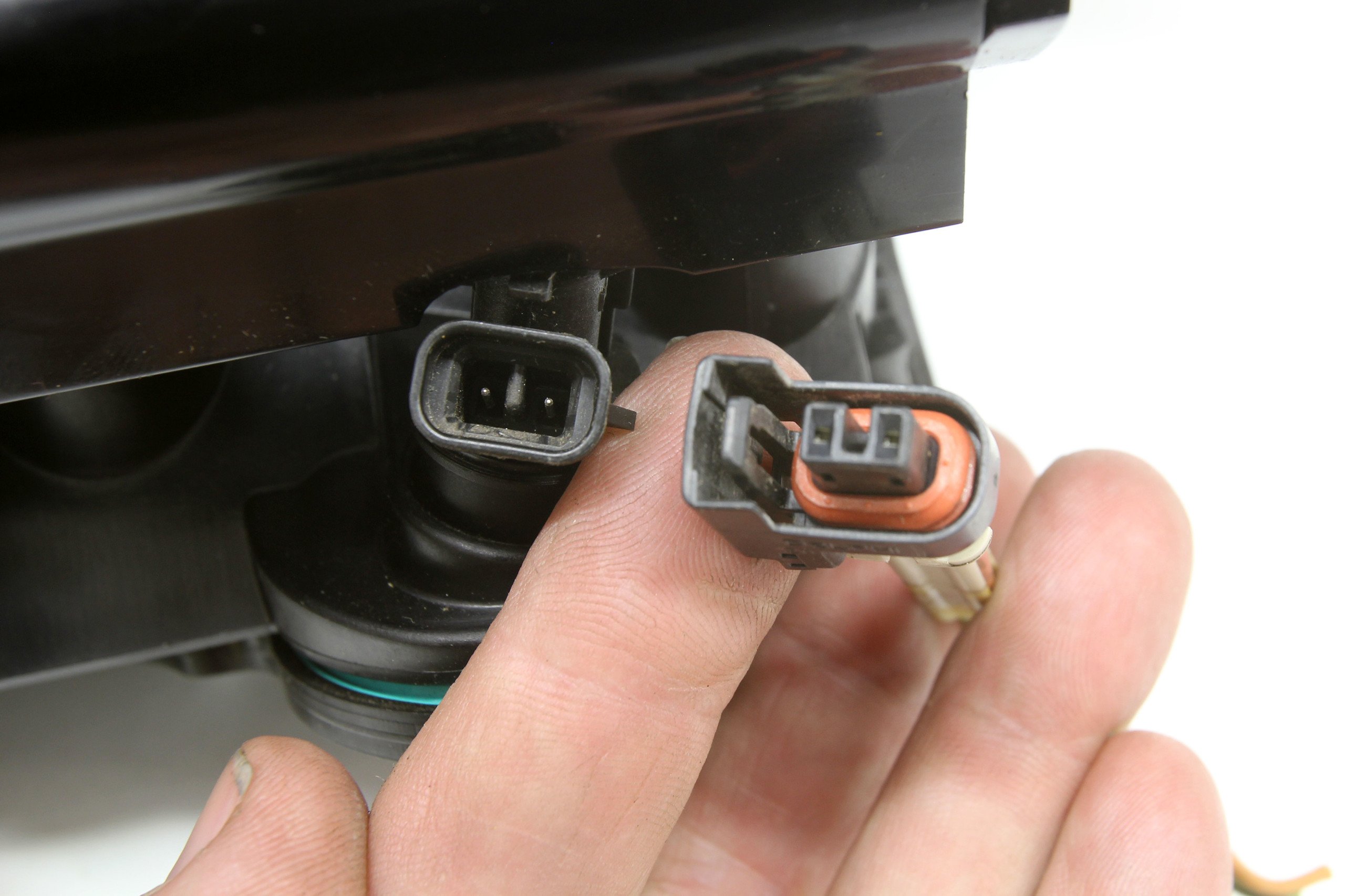
If you’re like us, you struggle to remember which plug is which. It’s hard to keep all these electronic fuel injector connector descriptions straight. So we created this cheat sheet with photos to make it easier to remember. There are several different injector electrical connectors but we’ll focus on the three most popular. The EV1 is different from the EV6 (which is also called a USCAR). Then there are the early GM truck injectors called the Multec. It can be confusing. We‘ve included a photo of each injector with its respective connector. Left is the EV6, middle is the EV1, and right is the GM Multec connector.
Lash and Piston-to-Valve Clearance
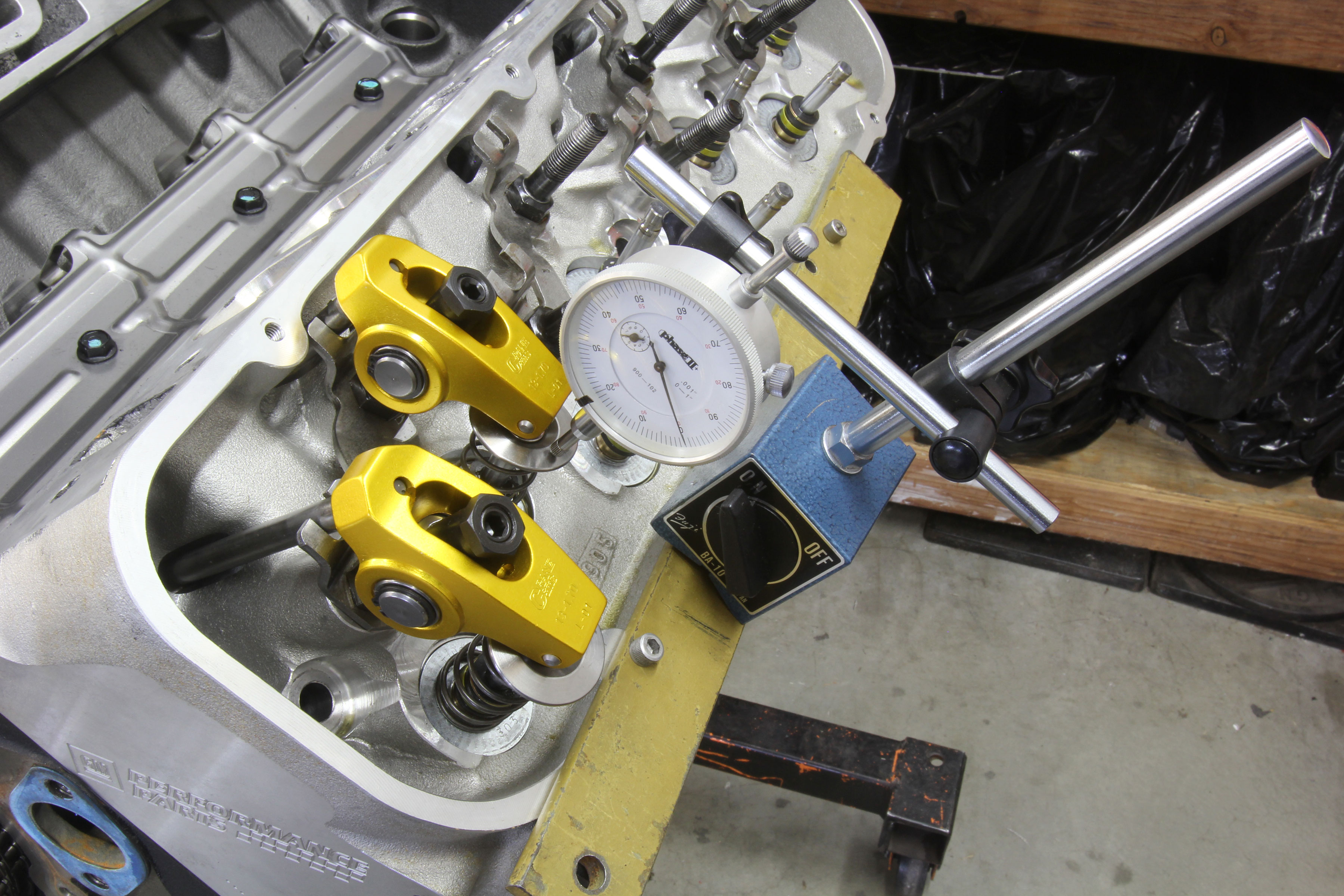
When checking piston-to-valve (P-to-V) clearance on a performance engine with a mechanical camshaft, always include the lash as this will affect the position of the valve in relation to the piston. It’s also more accurate to check using a dial indicator as opposed to the old clay method. Adding 0.020-inch lash can add more than that value to the piston-to-valve clearance because the lift curve essentially started later.
Generic minimum P-to-V clearance specs are 0.080-inch for the intake and 0.110-inch for the exhaust. However, some race engine builders suggest adding 0.010-inch to the engine’s piston-to-head clearance will also work. This assumes perfect control over the valvetrain. That may be a dangerous assumption to make so tread carefully here.
Given these specs, if the total piston-to-head distance is 0.042-inch (0.034-inch gasket + 0.008-inch piston below the deck = 0.042-inch), adding 0.010 = 0.052-inch of piston-to-valve clearance. Remember that if intake valve P-to-V is tight, you can retard the camshaft to add clearance. But retarding the cam will also make the exhaust P-to-V tighter. The opposite is also true where advancing the cam will decrease intake P-to-V but increase the exhaust.
Hopefully, one or more of these tech tips have resonated with you, and can help you avoid some of the pitfalls we’ve encountered along our journey. Keep an eye out for more of these, as we’ve got a lot more experience to share, and our journey is far from over.