If you seat a group of gearheads at a table, the topic of basic driveshaft angles can usually get responses ranging from “it’s no big deal” to practices of surgical precision. However, paying attention to vertical and side-by-side alignment — and even driveshaft phasing — can prevent calamity with every bit of additional horsepower you push to the ground. It is not about just the driveshaft, but also the alignment of your entire drivetrain.

A properly aligned driveshaft can fundamentally eliminate many problems often attributed to other components on a car. Whether it be a cruiser, performance, or an all-out drag car, several different problems can point to driveshaft misalignment.
Chasing a vibration most commonly points to a driveshaft problem. Many call it an “out of balance” driveshaft, but the culprit can have many sources. In a more performance and racing-oriented application, such problems as chatter and wheel hop can result. In extreme horsepower and torque situations, a pulsing transfer of power is a source for radical suspension and tire shake.
Transmission And Pinion Angle Alignment
The U-joint angles at the front and rear of the driveshaft are the most common sources for alignment problems. When a hot rod or race car undergoes any suspension modifications, too much misalignment between these points can occur.
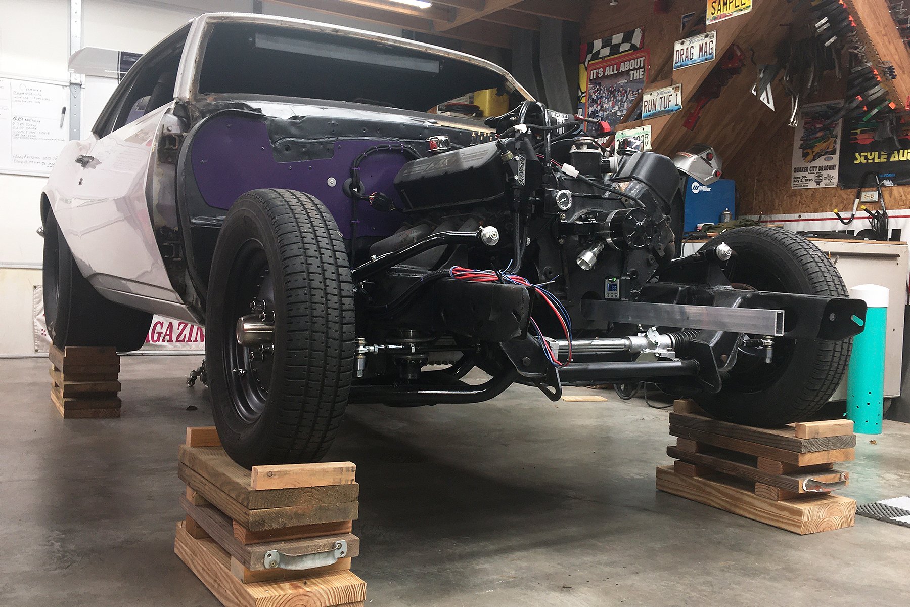
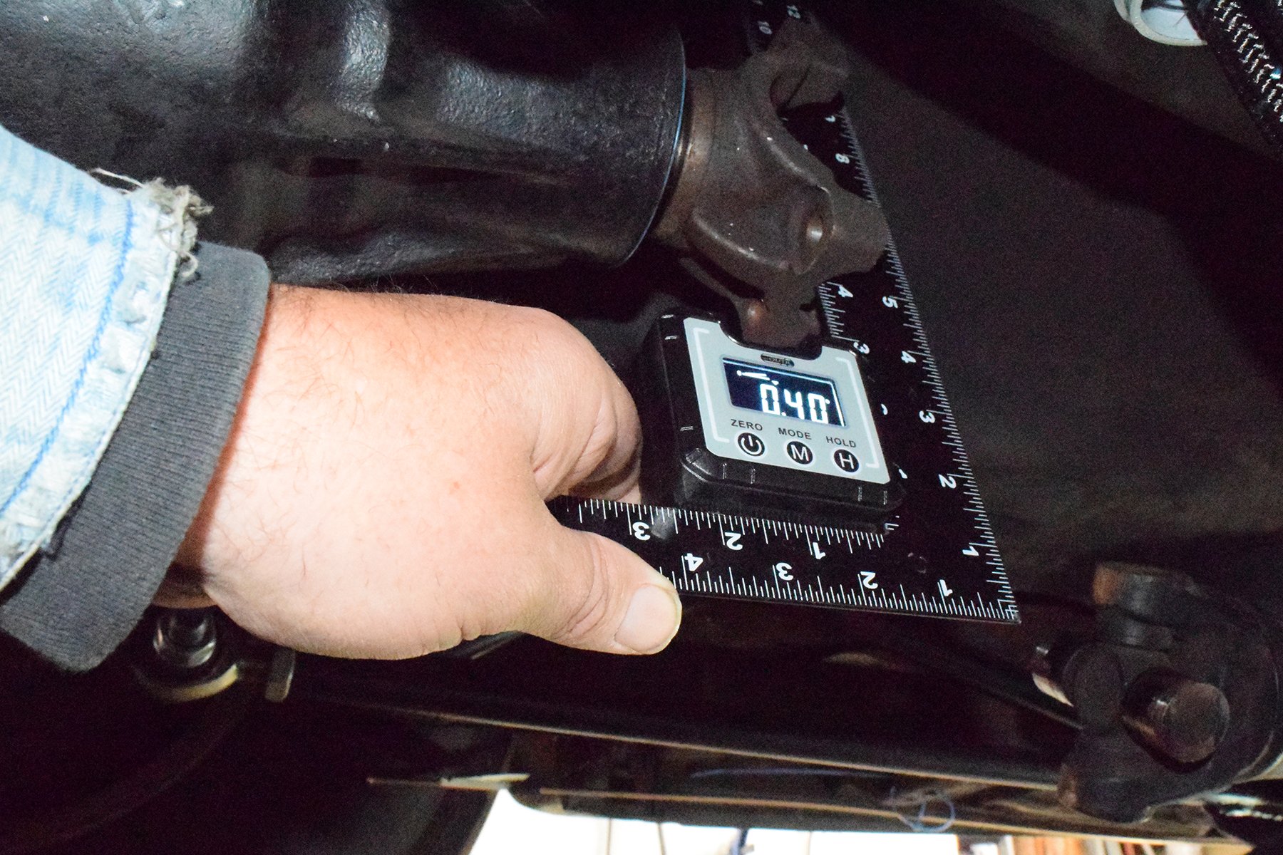
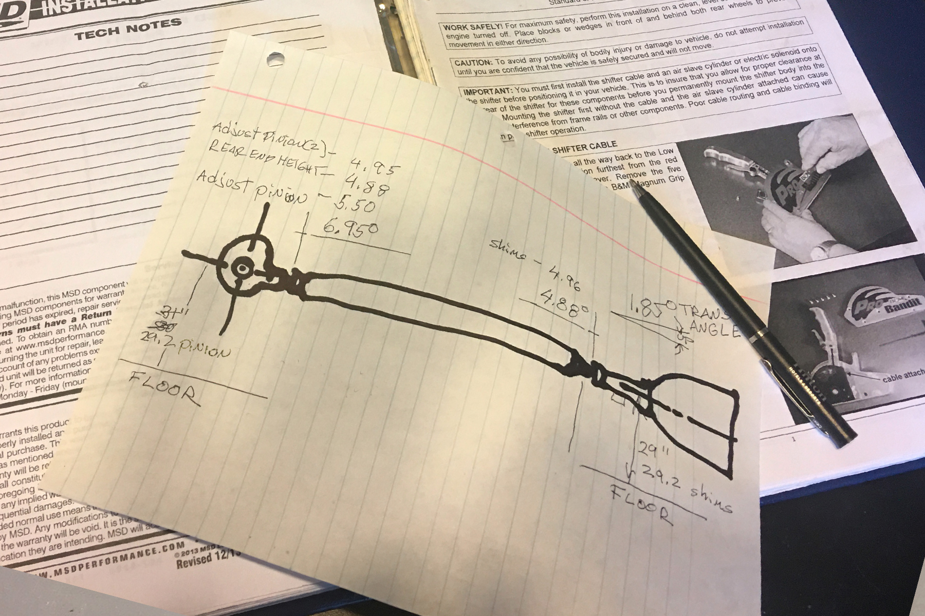
With our current project Camaro elevated and level, our starting point is to log our transmission angle. We can now compare our front and rear u-joint angles for overall misalignment.
Our starting point is to get the transmission and rearend yokes matched as closely in height with each other as possible from the floor surface. With our heights close, we begin adjusting the rear pinion angle to match the transmission. As a general rule, the angles at each U-joint should not exceed 5-degrees. An even tighter tolerance is highly recommended as your horsepower increases.
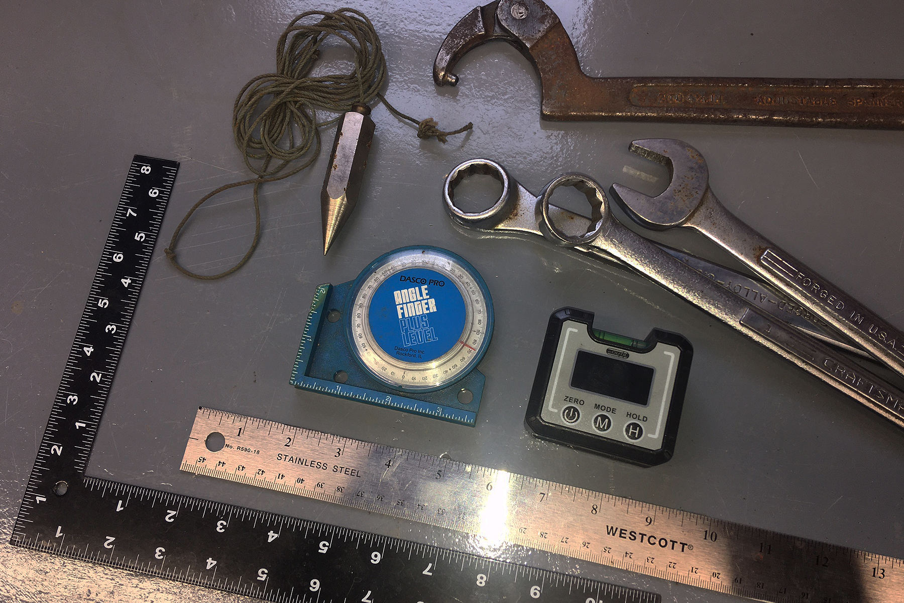
You can use either a digital or analog angle meter to make your adjustments. A little patience combined with an array of suspension wrenches, a square, and straight edge, and a plumb bob will get the job completed.
Measure, Adjust, Measure Again
Though we have elevated our project car evenly off our shop floor, it is most critical to begin measuring with your rear suspension sitting as if it is ready for the road or track.
Your front suspension positioning is not as critical, because you are beginning the measuring process from the engine/transmission centerline, whatever that is. You simply measure the current angle as it sits, and deduct that number from your following yoke and U-joint measurements.
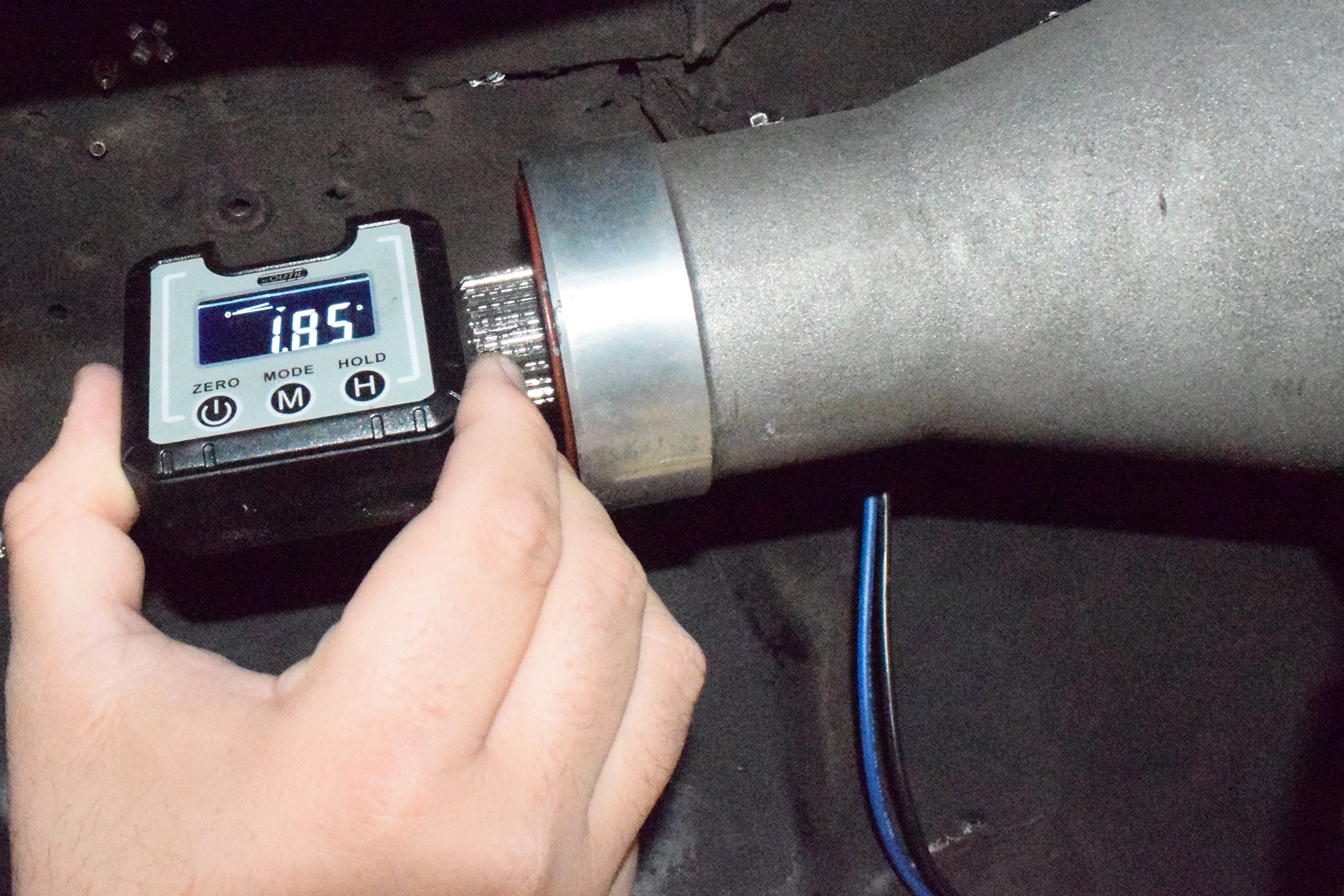
For example, our engine/transmission is at a 1.85-degree upward angle. Our pinion is at a 5-degree downward angle as a starting measure. That means our current driveshaft angle is heavily misaligned at 6.85-degrees. With that, we adjust our pinion angle upward to match the 1.85-degree transmission angle while continuing to adjust, measure, adjust, and measure. We continue to measure the angle of each U-joint face. Note that if your transmission and pinion angles are genuinely parallel from step one, each U-joint angle will be identical.
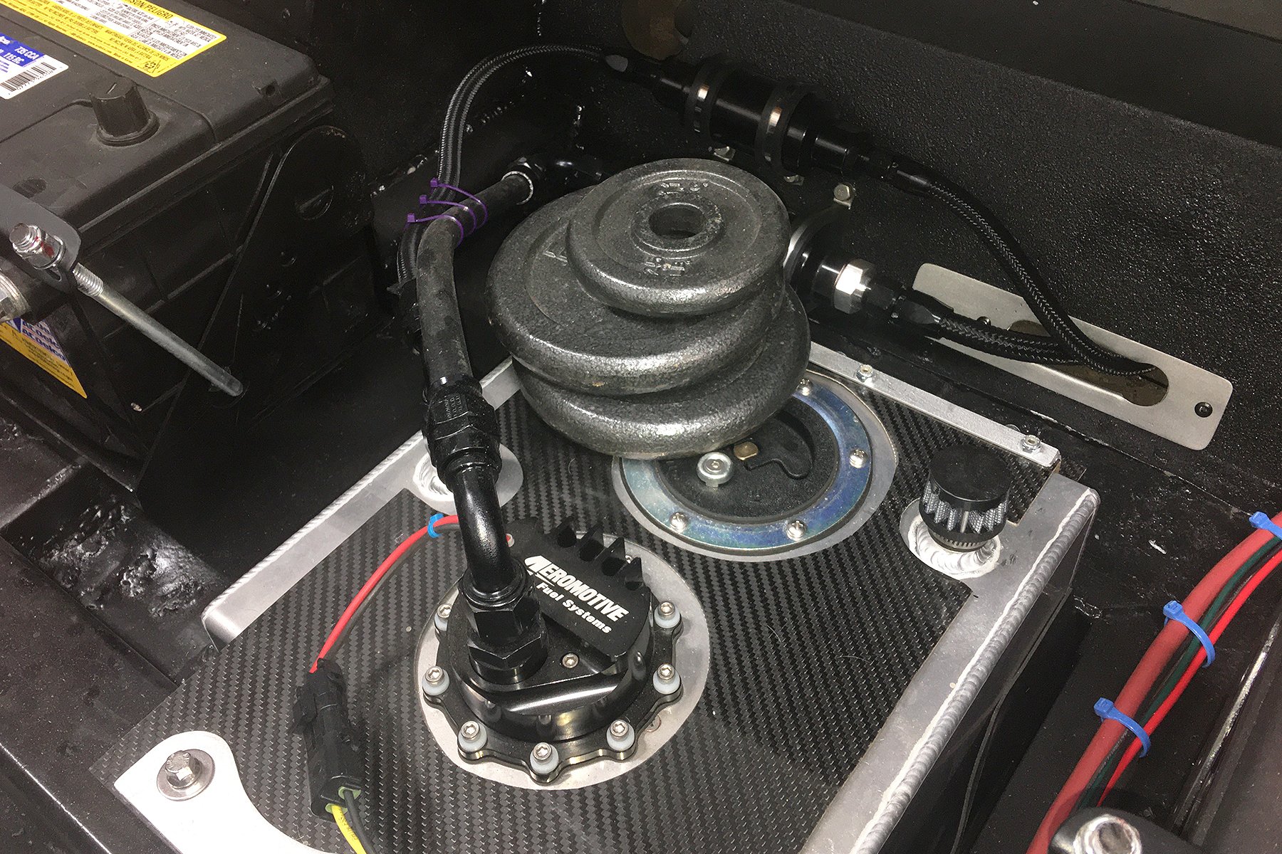

Make sure all of your typical weight balances on your chassis are reasonably simulated so your suspension is compressed accordingly. For example, we used steel weights to simulate a full tank of fuel and a driver in the seat.
Changing the rear pinion-angle adjustment requires the most effort. A leaf spring or truck-arm-style suspension can use axle shims or wedges at the mounting perch to alter the pinion angle. With many three-link, four-link, or ladder bar suspensions, a threaded adjustment coupler is incorporated into the suspension components.
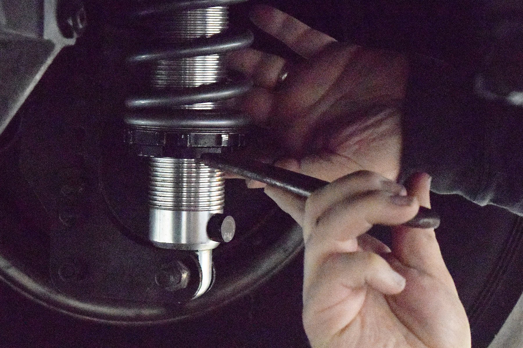
We adjusted our coil-over shocks so the distance from the ground to our pinion yoke is the same dimension as it is from the ground to the transmission yoke. The process of matching heights and angles at each U-joint typically takes multiple adjustments.
Our project Camaro’s case is a prime example of needing adjustments; with large diameter slicks and ladder bar suspension, our geometry is drastically different from stock. Additionally, with factory-style engine mounts still in place, we had no idea if the previous owners had our suspension angles appropriately adjusted, and it was not correct.
In our case, the pinion angle is moved by an adjusting nut on the ladder bars. It is also an exercise in detail to occasionally reaffirm your entire rearend remains square in the chassis during these continued adjustments. By adjusting and re-adjusting the suspension height and re-establishing our proper pinion angle, we were able to get our U-joint alignment down to within less than 2-degrees for our application.
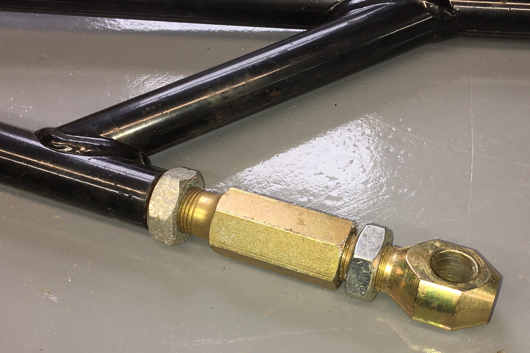
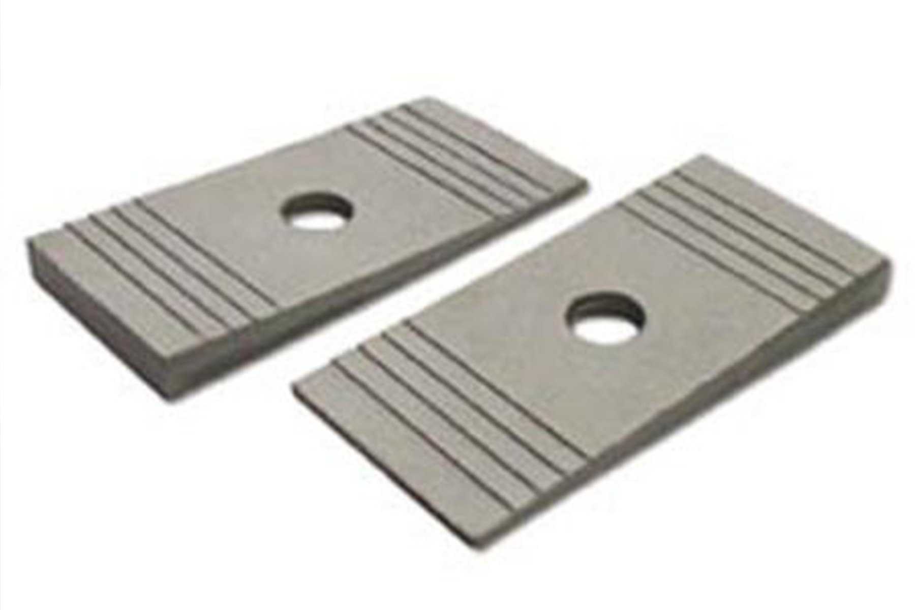
Ladder bar and four-link suspensions typically have threaded adjusters to help achieve your pinion angle. Leaf spring suspension can use popular spacers and wedges of different angles between the leaves and axle-mounted spring perch.
Offset Alignment
Many rodders and racers with factory or modified factory chassis assume that the left-to-right (offset alignment) of the driveshaft angle is already correct. From 1950’s-era cars to today, various manufacturers offset the entire engine differently, based on the engine size and torque characteristics, even within the same model car. As an example, the Camaro has different engine offsets (towards the passenger side) as much as 1 1/2-inches, depending on whether a six-cylinder, small block, or big block was under the hood.
It will typically take multiple adjustments for everything to ultimately align. We log each adjustment and then save those settings in our car’s logbook for future reference.
These offsets were engineered into a bone-stock drivetrain to counteract any torque-based drivability for a novice driver. The factory differential is factory offset by 1/2-inch to the right of center for the same reasons.
These angles may not be detrimental to an all-factory car, but when you start adding suspension modifications along with performance engines and transmissions, these angle attributes could be as critical as any other misalignment.

In our multiple adjustment steps, we decided to add a small shim under our transmission mount. By raising our transmission centerline, we lessen the adjustment necessary at our shocks to match the two heights.
Our Camaro has spent most of its life as a Super/Stocker and has been equipped with a plethora of small block, big block, and varied manual and automatic transmission combinations over the years. Considering that history, we thought it was necessary to be certain that our side-to-side alignment is proper.
Most race car, pro street, and autocross chassis builders will fabricate a chassis with a drivetrain centered within a vehicle. This allows for overall balancing on the four corners by using wheel scales. Any chassis adjustments then take place with shock and suspension-link tuning. With a wealth of plumb bob markings on our shop floor, we matched OEM chassis holes on our front crossmember to establish a dead centerline throughout the car’s length. We now know our engine, transmission, and differential are currently centered within the chassis.
Driveshaft Phasing
Driveshaft phasing is the process of “clocking” the driveshaft as it relates to the front and rear yokes. The common automotive driveshaft is built with each end in exact relation to each other. This phasing has each U-joint mount at each shaft end in the same phased position.
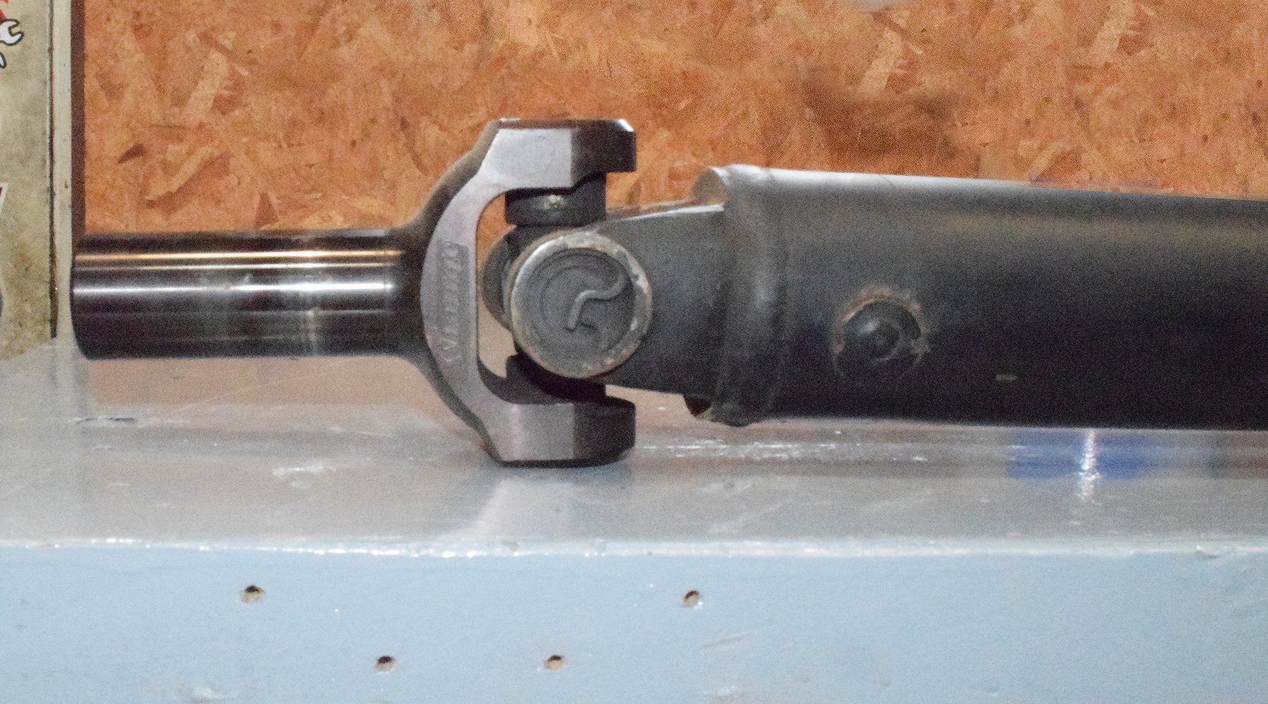
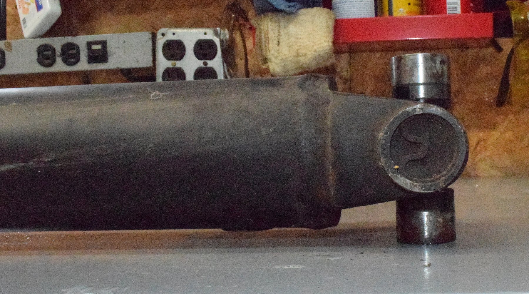
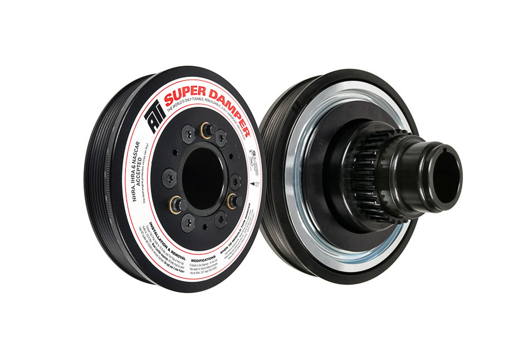
A properly phased driveshaft places both U-joints in exact axial alignment. Even a home-brew shaft with just a couple of degrees of twist in that alignment can cause big problems. Even with our professional-built shaft, we found a balancing washer missing. It was time to get it checked and rebalanced by a shop with performance experience.
Though precise phasing is the duty of a good driveshaft shop, many driveshaft kits rely on the enthusiast to get this adjustment correct. When you look down your driveshaft from the end (such as looking at a pool cue), if the front and rear yoke are even slightly out of phase by a couple of degrees, vibration at speed is almost inevitable.

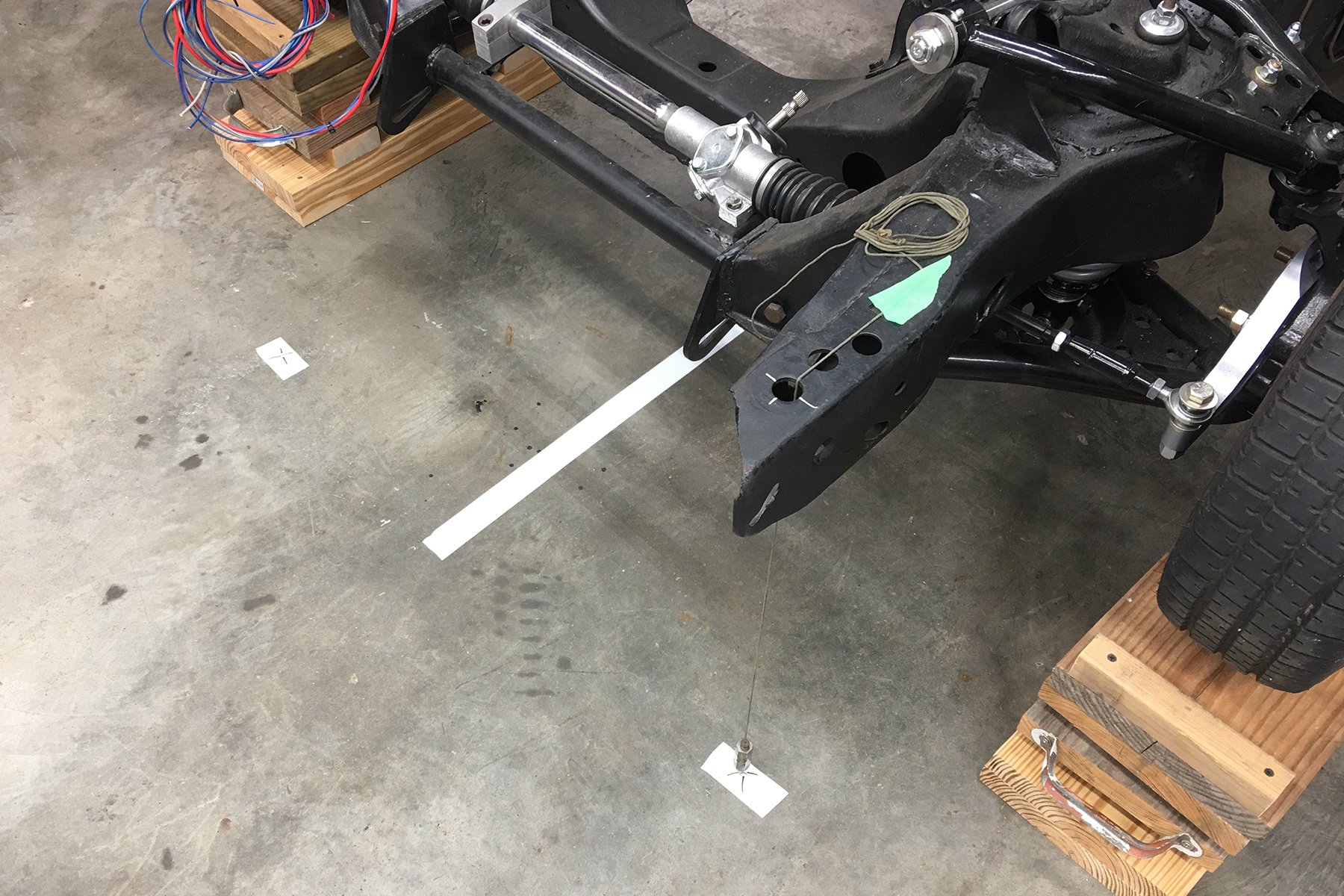
We used a plumb bob and multiple chassis mounts to establish our chassis centerline for the length of the drivetrain. We have confirmed that the engine, transmission, driveshaft, and differential are all inline. This Camaro has seen countless drivetrain swaps over the years, so you never know where the alignment is from the front to the back of the car.
Master The Art Of Alignment
When you understand how a misaligned driveshaft can physically speed up and slow down as it transfers power from the front to the rear, you will begin to understand its source as a vibration point or worse, as a point of failure.
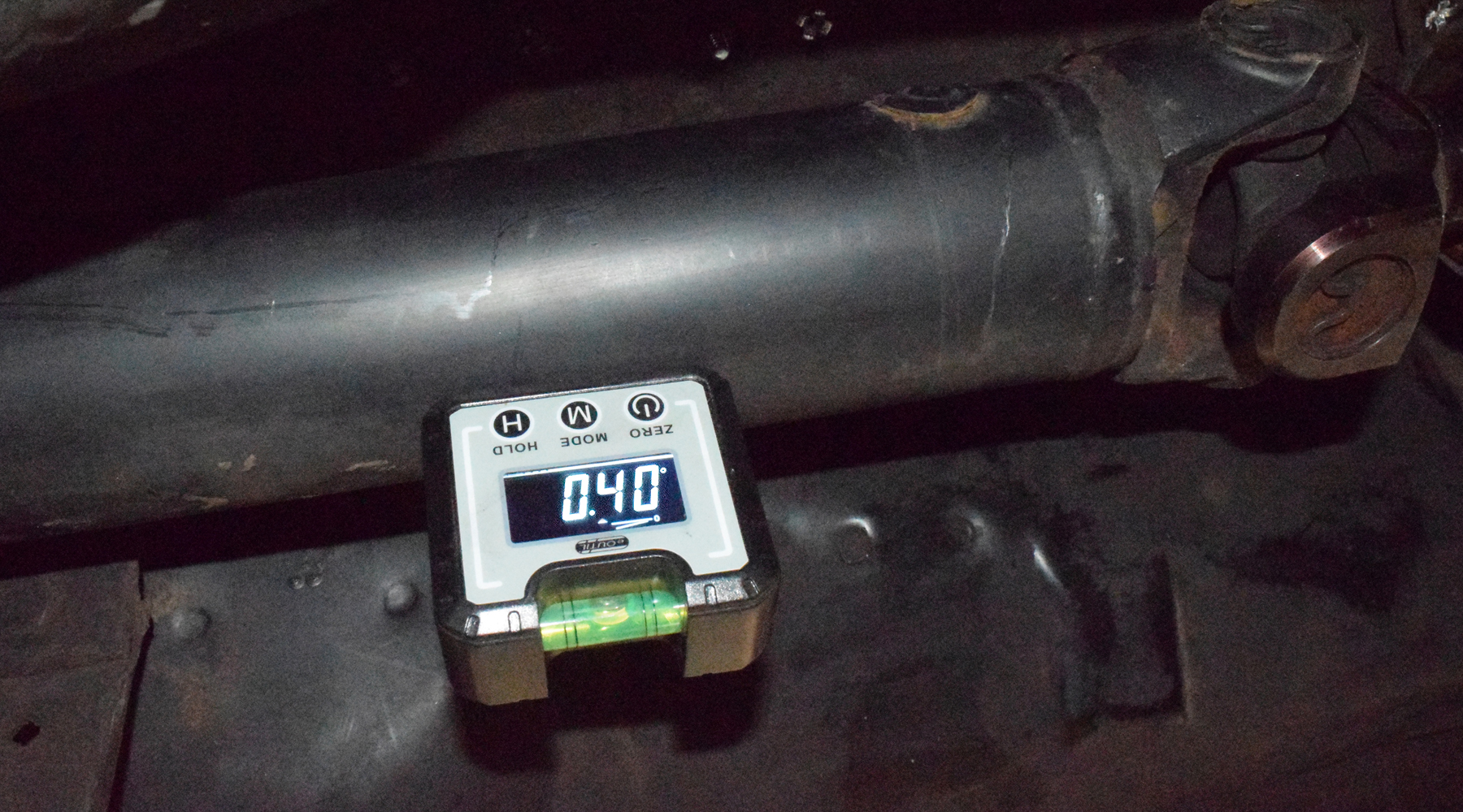
A general rule is that the driveshaft angles should not exceed 5-degrees. Subtracting our original engine angle, we have carefully set ours at less than 2-degrees at each u-joint. Once adjusted, it is handy to keep logs and apply your angle finder down the road to make sure nothing has changed.
We have all heard the story of the incurable vibration in someone’s hot rod. Scrutinizing the various U-joint angles and overall alignment from the engine to the rear yoke may be a time-consuming effort, but it’s one that is well worth the effort when it comes to a vibration-free outcome.